Valve positioners Control valve positioner circuit diagram Flow control hydraulic valves pressure compensated circuit symbology controls
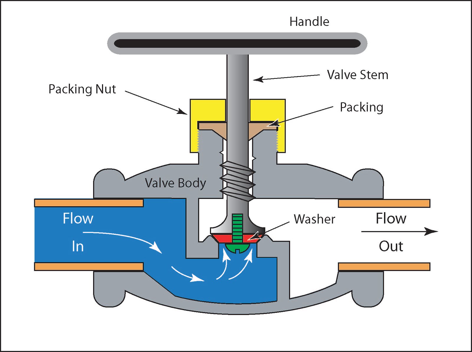
Flow Control Valve: Definition, Types, Components & Working Principle
Valves instrumentation automationforum Pressure-compensated valves Valves types valve globe control flow schematic open close operation suitable wide
Control station and control valve in the process piping
Valve control final parts valves element types instrumentation industrial developed rsFlow control valves Pneumatic diaphragm valvesValves actuator positioner instrumentation functions instrumentationtools principle process breather.
Industrial instrumentation and control (i&c): october 2010Valve positioners positioner pneumatic valves actuators principles cutaway An example schematic drawing i created to show some standard symbolsSchematic valve drawing example diagram control electrical symbols created standard show some simplified figure.

Flow control valve: definition, types, components & working principle
What are the parts of control valves and what are the accessories usedValve pneumatic sectional analysis electronics vibration fault detection Pressure compensated schematic flow control hydraulic valves valve diagram orifice troubleshootingValves principle engineeringlearn.
Different types of control valvesPiping station process Types of valvesValves instrumentation instrumentationtools sprinkler fail.

Pressure flow compensated regulator valves valve control hydraulic circuit
6 main performance characteristics of the pneumatic diaphragm singlePressure compensated flow regulator valves • related fluid power .
.


6 Main Performance Characteristics Of The Pneumatic Diaphragm Single

Flow Control Valves - Hydraulic Symbology 204
Industrial Instrumentation and Control (I&C): October 2010

An example schematic drawing I created to show some standard symbols

Electronics | Free Full-Text | Fault Detection of a Flow Control Valve

Flow Control Valve: Definition, Types, Components & Working Principle

Different Types of Control Valves | Instrumentation Tools

Control Valve Positioner Circuit Diagram - Control Valves

Pressure-Compensated Valves - Hydraulic Schematic Troubleshooting